In 2010, Beacon Power began testing of their Smart Energy 25 (Gen 4) flywheel energy storage system at a wind farm in Tehachapi, California. The system was part of a wind power and flywheel demonstration project being carried out for the California Energy Commission. . Flywheel energy storage (FES) works by spinning a rotor () and maintaining the energy in the system as . When energy is extracted from the system, the flywheel's rotational speed is reduced as a consequence of the. . A typical system consists of a flywheel supported by connected to a . The flywheel and sometimes. . TransportationAutomotiveIn the 1950s, flywheel-powered buses, known as . • • • – Form of power supply• – High-capacity electrochemical capacitor . GeneralCompared with other ways to store electricity, FES systems have long lifetimes (lasting decades with little or no. . Flywheels are not as adversely affected by temperature changes, can operate at a much wider temperature range, and are not subject to many of the common failures of chemical . They are also less potentially damaging to the environment, being largely made of . • Beacon Power Applies for DOE Grants to Fund up to 50% of Two 20 MW Energy Storage Plants, Sep. 1, 2009• Sheahen,.
[PDF Version]
First-generation flywheel energy-storage systems use a large steel flywheel rotating on mechanical bearings. Newer systems use carbon-fiber composite rotors that have a higher tensile strength than steel and can store much more energy for the same mass. . Flywheel energy storage (FES) works by spinning a rotor () and maintaining the energy in the system as . When energy is extracted from the system, the flywheel's rotational speed is reduced as a consequence of the. . A typical system consists of a flywheel supported by connected to a . The flywheel and sometimes. . TransportationAutomotiveIn the 1950s, flywheel-powered buses, known as . • • • – Form of power supply• – High-capacity electrochemical capacitor . GeneralCompared with other ways to store electricity, FES systems have long lifetimes (lasting decades with little or no. . Flywheels are not as adversely affected by temperature changes, can operate at a much wider temperature range, and are not subject to many of the common failures of chemical . They are also less potentially damaging to the environment, being largely made of . • Beacon Power Applies for DOE Grants to Fund up to 50% of Two 20 MW Energy Storage Plants, Sep. 1, 2009• Sheahen,.
[PDF Version]
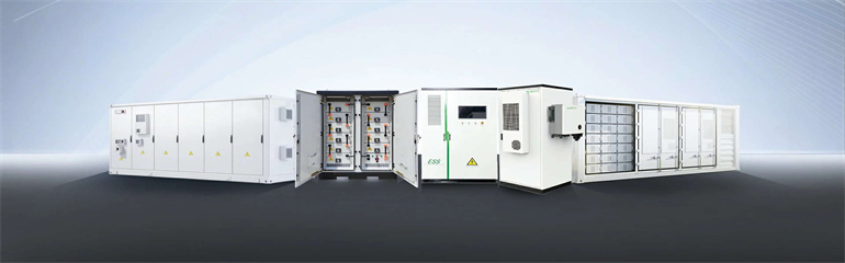
Battery energy storage systems can enable EV fast charging build-out in areas with limited power grid capacity, reduce charging and utility costs through peak shaving, and boost energy storage capacity to allow for EV charging in the event of a power grid disruption or outage. It is an informative resource that may help states, communities, and other stakeholders plan for EV infrastructure deployment, but it is not intended to be used. . The EV charging network is categorized into three levels, each serving different needs: Level 1 Chargers: Commonly used in residential settings, these standard chargers offer a slow but steady charging solution, making them ideal for overnight use. They typically deliver charging through a 120-volt. . EVB delivers smart, all-in-one solutions by integrating PV, ESS, and EV charging into a single system. They offer numerous benefits, including improved grid stability, optimized energy use, and a promising return on investment (ROI). It highlights how integrating and co-locating these systems with renewable energy sources, such as solar and wind, can help stabilize and optimize grid operations.
[PDF Version]
An example of an LSM launched roller coaster is Maverick at Cedar Point in Sandusky, Ohio. These launch systems transfer electricity through a motor on the roller coaster's track so that it controls the speed at which it will urge the cars and train either forward or backward on a segment. . The launched roller coaster is a type of that initiates a ride with high amounts of acceleration via one or a series of (LIM), (LSM),, tires, chains, or other mechanisms employing . Hydraulic fluid-launched roller coasters, pioneered by manufacturer, give the riders greater acceleration with improved smoothness over the electromagnetic and catapult launch mechanisms. The acceleration from a. . Australia• ()• ()• ()• () . LIM / LSMLinear induction motor (LIM) and linear synchronous motor (LSM) coasters use propulsion via . Eddy current launcher (LEM)Magnets are placed under the cars and a series of coupled to aluminum discs is in the launch zone:.
[PDF Version]
Sinomach Heavy Equipment Group Co (Sinomach-HE) rolled out a new flywheel energy storage product on July 23. It is characterized by high energy storage density as well as high efficiency and low cost, and is pro-environment with longer service life and better adaptability. The technology allows for rapid energy discharge and recharge cycles, making it suitable for various applications such as grid. . flywheel energy storage systems are reviewed. The energy is present in the flywheel to provide higher power for a shorter duration, the peak output designed for 125 kw for 16 seconds ansfer, hy rid electric vehicles, and many. . Flywheel energy-storage product is an energy-storage device of mechanical and electrical energy conversion, breaking the limit of chemical battery and storing the energy by means of physical method. Based. . Flywheels are an excellent mechanism of energy storage for a range of reasons, starting with their high efficiency level of 90% ??? A flywheel is an inertial energy storage device. It absorbs mechanical energy and serves as a reservoir, storing energy during the period when the supply of energy is. .
[PDF Version]
Superconducting energy storage systems utilize superconducting magnets to convert electrical energy into electromagnetic energy for storage once charged via the converter from the grid, magnetic fields form within each coil that is then utilized by superconductors as magnets and. . Superconducting energy storage systems utilize superconducting magnets to convert electrical energy into electromagnetic energy for storage once charged via the converter from the grid, magnetic fields form within each coil that is then utilized by superconductors as magnets and. . Superconducting magnetic energy storage (SMES) systems store energy in the magnetic field created by the flow of direct current in a superconducting coil that has been cryogenically cooled to a temperature below its superconducting critical temperature. This use of superconducting coils to store. . Superconducting Magnetic Energy Storage (SMES) is an innovative system that employs superconducting coils to store electrical energy directly as electromagnetic energy, which can then be released back into the grid or other loads as needed. External power charges the SMES system where it will be stored; when needed, that same power can be discharged and used externally. This flowing current generates a magnetic field, which is the means of energy storage.
[PDF Version]