Fig. 1 below shows some typical nitrogen tanks. A liquid nitrogen tank, also known as a cryogenic tank or dewar, is a specialized container designed for the storage and transportation of liquid nitrogen. . Storing nitrogen serves several important purposes across various industries and applications. Here are some common reasons for the storage of nitrogen: Inerting: Nitrogen is an inert gas, meaning. . The main components of a liquid nitrogen tank include: 1. Inner Vessel:This is the innermost chamber that holds the liquid nitrogen. It is usually. . A liquid nitrogen tank, also known as a cryogenic tank or dewar, is a specialized container designed for the storage and transportation of liquid nitrogen. Unlike nitrogen gas stored in compressed gas cylinders, liquid nitrogen is extremely cold and maintained at a. . Nitrogen tanks come in various sizes and capacities to cater to different needs and applications. The size of a nitrogen tank is typically determined by its capacity to hold compressed nitrogen.
[PDF Version]
“ Use of phase change materials in wood and wood-based composites for thermal energy storage: A Review,” BioResources 18 (4), 8781-8805. These materials have a large capacity for storing. . To address the low efficiency and flammability of wood-based phase change materials (WPCMs) in solar energy storage, this study developed a series of WPCMs (PEG/TPP/DW-P) with both flame retardancy and solar-thermal energy storage properties by vacuum-impregnating polyethylene glycol (PEG). . Wood, a renewable and abundant biomass resource, holds substantial promise as an encapsulation matrix for thermal energy storage (TES) applications involving phase change materials (PCMs). However, practical implementations often reveal a disparity between observed and theoretical phase change. . Here we report on a wood-phase change material (PCM) composite, referred to as PCM-wood, which holds potential for energy-eficient buildings. The composite shows excellent thermal regulation capability with a melting enthalpy of 113 J g 1 at 22 ◦C and solidification enthalpy of 114 J g 1 at 21 ◦C.
[PDF Version]
Candidate materials for (SSEs) include ceramics such as, , sulfides and . Mainstream oxide solid electrolytes include Li1.5Al0.5Ge1.5(PO4)3 (LAGP), Li1.4Al0.4Ti1.6(PO4)3 (LATP), perovskite-type Li3xLa2/3-xTiO3 (LLTO), and garnet-type Li6.4La3Zr1.4Ta0.6O12 (LLZO) with metallic Li. The thermal stability versus Li of the four SSEs was in order of LAGP < LATP < LLTO < LLZO. Chloride superionic conductors have been proposed as anoth.
[PDF Version]
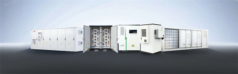
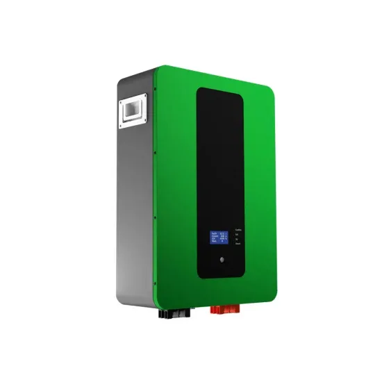
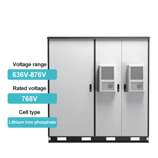
pioneered LFP along with SunFusion Energy Systems LiFePO4 Ultra-Safe ECHO 2.0 and Guardian E2.0 home or business energy storage batteries for reasons of cost and fire safety, although the market remains split among competing chemistries. Though lower energy density compared to other lithium chemistries adds mass and volume, both may be more tolerable in a static application. In 2021, there.
[PDF Version]
Pumped-storage hydroelectricity (PSH), or pumped hydroelectric energy storage (PHES), is a type of hydroelectric energy storage used by electric power systems for load balancing. A PSH system stores energy in the form of gravitational potential energy of water, pumped from a lower elevation reservoir to a higher elevation. Low-cost surplus off-peak electric power is typically used. Basic principleA pumped-storage hydroelectricity generally consists of two water reservoirs at different heights, connected with each other. At times of low electrical demand, excess generation capacity is used to pump water into the up. . In closed-loop systems, pure pumped-storage plants store water in an upper reservoir with no natural inflows, while pump-back plants utilize a combination of pumped storage and conventional . Taking into account conversion losses and evaporation losses from the exposed water surface, of 70–80% or more can be achieved. This technique is currently the most cost-effective means of storing large amo.
[PDF Version]
Electricity can be stored directly for a short time in capacitors, somewhat longer electrochemically in, and much longer chemically (e.g. hydrogen), mechanically (e.g. pumped hydropower) or as heat. The first pumped hydroelectricity was constructed at the end of the 19th century around in Italy, Austria, and Switzerland. The technique rapidly expanded during the 1960s to 1980s,.
[PDF Version]