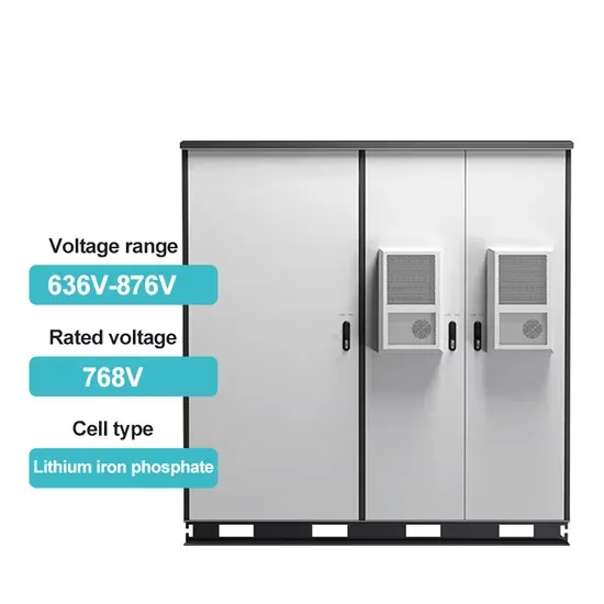
Liquid flow energy storage principle diagram
The fundamental difference between conventional and flow batteries is that energy is stored in the electrode material in conventional batteries, while in flow batteries it is stored in the electrolyte. . A flow battery, or redox flow battery (after ), is a type of where is provided by two chemical components in liquids that are pumped through the system on. . A flow battery is a rechargeable in which an containing one or more dissolved electroactive elements flows through an . The cell uses redox-active species in fluid (liquid or gas) media. Redox flow batteries are rechargeable () cells. Because they employ rather than or they are more similar to fuel cells than to conventional. . Compared to inorganic redox flow batteries, such as vanadium and Zn-Br2 batteries, organic redox flow batteries' advantage is the tunable redox properties of their active components. As of. . The (Zn–Br2) was the original flow battery. John Doyle file patent on September 29, 1879. Zn-Br2 batteries have relatively high specific energy, and were demonstrated. . Redox flow batteries, and to a lesser extent hybrid flow batteries, have the advantages of:• Independent scaling of energy (tanks) and power (stack), which allows for a cost/weight/etc.. . The hybrid flow battery (HFB) uses one or more electroactive components deposited as a solid layer. The major disadvantage is that this reduces decoupled. [PDF Version]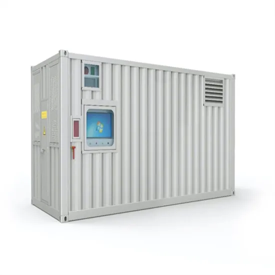
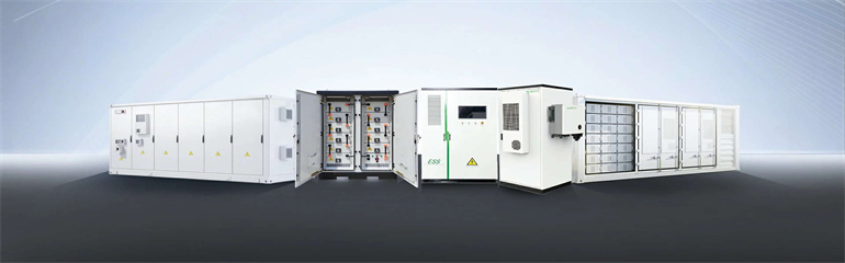
Energy storage container wiring specifications
Topos energy storage CCS, flexible customization: injection molding or blister insulation board can be selected for Bracket; wire harness, FPC, or PCB can be selected for the collection. . ign and development of a containerized energy storage system. - Define the desired energy capaci y (in kWh) and power output (in kW) based on the. . ers lay out low-voltage power distribution and conversion for a b de ion – and energy and assets monitoring – for a utility-scale battery energy storage system entation to perform the necessary actions to adapt this reference design for the project requirements. ABB can provide support during all. . rage applications in commercial and industrial environments. The containerized configuration is a single container with a power conversion system, switchgear, racks of batteries, HV C units and all associated fire and safety equipment inside. These systems are designed to store energy from renewable sources or the grid and release it when required. [PDF Version]FAQS about Energy storage container wiring specifications
How many mw can a battery energy storage system handle?
the load when needed, reducing the use of diesel generators. The battery energy storage system can also be used continuously to .6 MWh1.1 MW / 1.2 MWhBattery warran ISO container. 2590 mm and other high humidi y/ corrosive applicationsFire alarmIncluded as standa
What is energy storage system?
Energy Storage System developed by CATL. It describes and stipulates the performance index, basic functions, interface and communication, key parameters, safety characteristics, this product, as well as matters needing attenti n of users and relevant legal statements.The specifications and parameters of t
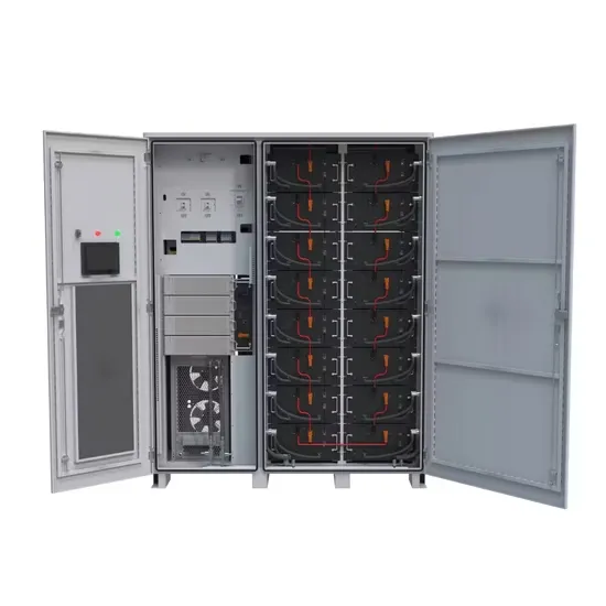
What is a containerized power conversion system?
rage applications in commercial and industrial environments. The containerized configuration is a single container with a power conversion system, switchgear, racks of batteries, HV C units and all associated fire and safety equipment inside. It can be deployed quickly to expand existing power
Is Eaton xstorage a containerized energy storage system?
nerContainerized energy storage systemAll-in-one containe Eaton xStorage is now available in a containerized version. This all-in-one, ready-to-use solution is the perfect choice for energy st
Does ENERC+ container have an integrated UPS system?
red area significantly.Independent UPS. EnerC+ container have integrated two UPS system, one is for FSS which available capacity is 24 hours, another one is for is 10 minutes3 System Specifications In this chapter, the systems sp cifications will be introduced in detai ironmental specifications, the mechanicals
Can a battery storage system increase power system flexibility?
sive jurisdiction.—2. Utility-scale BESS system description— Figure 2.Main circuit of a BESSBattery storage systems are emerging as one of the potential solutions to increase power system flexibility in the presence of variable energy resources, suc
Relationship diagram between energy storage power station and power grid
Electricity can be stored directly for a short time in capacitors, somewhat longer electrochemically in, and much longer chemically (e.g. hydrogen), mechanically (e.g. pumped hydropower) or as heat. The first pumped hydroelectricity was constructed at the end of the 19th century around in Italy, Austria, and Switzerland. The technique rapidly expanded during the 1960s to 1980s,. [PDF Version]
Energy storage capacitor wiring method
This chapter covers various aspects involved in the design and construction of energy storage capacitor banks. Methods are described for reducing a complex capacitor bank system into a simple equivalent circuit made up of L, C, and R elements. Dielectric capacitors encompass film capacitors, ceramic dielectric capacitors, and electrolytic capacitors, whereas supercapacitors can be further categorized into double-layer capacitors. . Charge Card Method Install the Charge Card on the capacitor. Connect the RED wire to +12 volts and the BLK wire to chassis ground. The capacitor is charged when green LED goes out and should take a matter of seconds to complete. If you're aiming for a stable charge retention, a parallel connection is optimal. Each face of the block is configurable for receiving power (blue), sending power (orange), or not transmitting (no plug). on a. . whether you're installing solar panels in Arizona or setting up a battery storage system in Bavaria, proper energy storage device wiring methods make the difference between a system that hums like a Beethoven symphony and one that crackles like microwave popcorn. Charging an Energy Storage Capacitor Many capacitor manufacturer"s supply a resistor (20 Ohm to 50 Ohm, 1-watt resistor) or. . [PDF Version]
Hydraulic energy storage valve assembly diagram
! WARNING – Before installing product, read and understand all warnings, safety labels and instructions. Failure to do so could result in SERIOUS INJURY!. . ! WARNING: If the valve spool binds or will not rotate freely . Manufacturing Company, Inc. WARNING: Do not use these valves on applications where property damage or personal . “A” PORT TO CYLINDER “B” PORT TO CYLINDER “OUT” PORT TO FROM PUMP RESERVOIR TO “IN” PORT . 4-way control valve designed to operate a two-way hydraulic circuit from a single hydraulic source ! WARNING: If the valve will not hold in detent – discontinue use at once. Return valve for repair. Serious injury could result. ! WARNING: CONTAMINATION – Energy strongly. [PDF Version]