Understanding the Basics of a 3 Phase Inverter
Understanding the complete schematic and diagram of a 3 phase inverter is crucial for designing, analyzing, and troubleshooting electrical systems that utilize this
View Details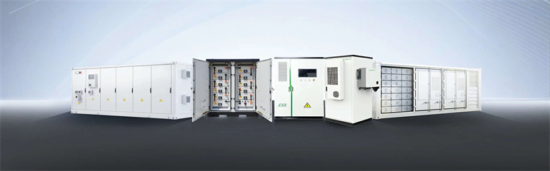
Understanding the complete schematic and diagram of a 3 phase inverter is crucial for designing, analyzing, and troubleshooting electrical systems that utilize this
View Details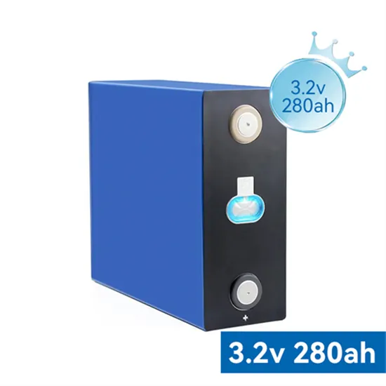
This application note outlines the most relevant power topology considerations for designing power stages commonly used in Solar Inverters and Energy Storage Systems (ESS).
View Details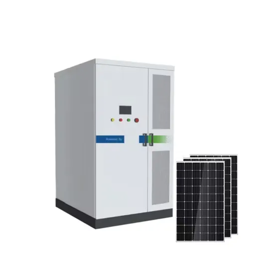
4.1 Introduction In this chapter the three-phase inverter and its functional operation are discussed. In order to realize the three-phase output from a circuit employing dc as the input voltage a three-phase
View Details
The circuit diagram of a three-phase inverter is shown below. The main function of this kind of inverter is to change the input of DC to the output of three-phase AC.
View Details
Four IQ Battery 5P units can be connected in a single 80 A circuit, with up to 12 IQ Battery 5P units supported across three phases. When designing a system, follow local regulations for system sizing.
View Details
A three-phase inverter system is operating at an output power level ranging from 10kW to above 300kW, used in commercial and decentralized utility-scale applications. High output power can be realized
View Details
A comprehensive engineering guide to NYISO interconnection modeling requirements, including steady-state, short-circuit, and dynamic studies.
View Details
The most common three-phase inverter topology is the Voltage Source Inverter (VSI), where a fixed DC voltage is converted into a variable AC output. The VSI employs six power switches (typically IGBTs
View Details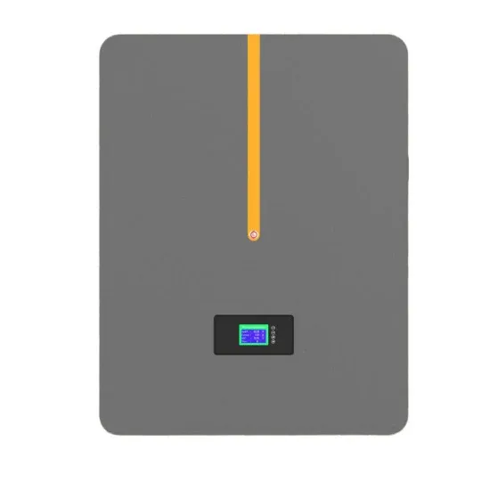
The electrochemical batteries provide a stable DC power supply for the energy storage system, and the DC power is converted to gridspecified AC power
View Details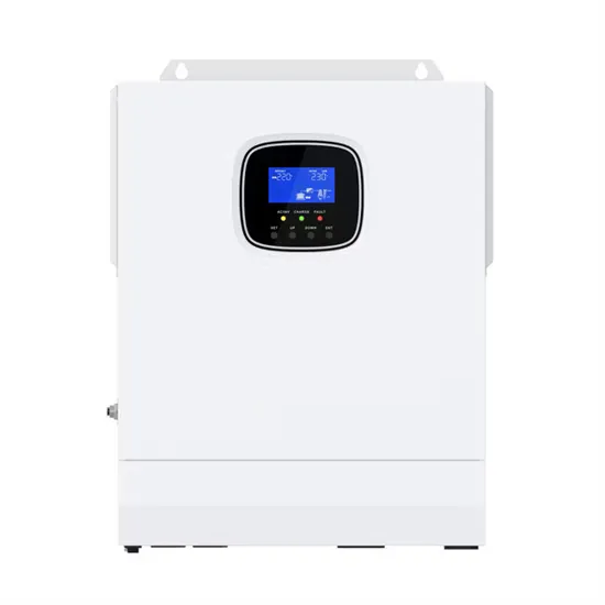
View and Download V-TAC VT-6605103 instruction manual online. HYBRID SOLAR INVERTER SINGLE PHASE. VT-6605103 inverter pdf manual download.
View Details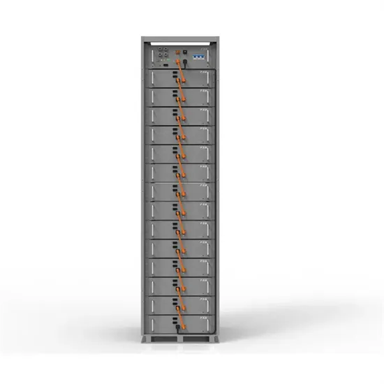
battery energy storage system is of three main parts; batteries, inverter-based power conversion system (PCS) and a Control unit called battery management system (BMS).
View Details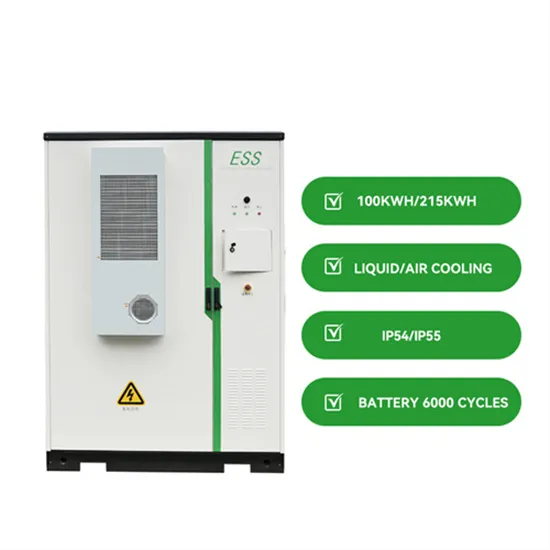
In this context, this study presents a three-phase transformerless battery storage system (BSS) based on a cascaded H-bridge inverter applied to
View Details
Stand-alone switched-mode power supply An adjustable switched-mode power supply for laboratory use A switched-mode power supply (SMPS), also called
View Details
One might think that to realize a balanced 3-phase inverter could require as many as twelve devices to synthesize the desired output patterns. However, most 3-phase loads are connected in wye or delta,
View Details
This reference design provides an overview into the implementation of a GaN-based single-phase string inverter with bidirectional power conversion system for Battery Energy Storage Systems (BESS).
View Details
Cascaded Multilevel Inverter is a 3-phase inverter designed for electric utility applications, offering precise control by employing multiple voltage levels to create a stepped waveform.
View Details
Below is a three-phase inverter circuit diagram designed using thyristors & diode (for voltage spike protection) And below is a three-phase inverter circuit diagram designed using only switches.
View Details
The study focuses on the interphase power imbalance problem in the cascaded multilevel energy storage inverter for ultra-high-speed linear motor propulsion (UHSLMP) systems. The traditional
View DetailsPDF version includes complete article with source references. Suitable for printing and offline reading.