This chapter covers various aspects involved in the design and construction of energy storage capacitor banks. Methods are described for reducing a complex capacitor bank system into a simple equivalent circuit made up of L, C, and R elements. Dielectric capacitors encompass film capacitors, ceramic dielectric capacitors, and electrolytic capacitors, whereas supercapacitors can be further categorized into double-layer capacitors. . Charge Card Method Install the Charge Card on the capacitor. Connect the RED wire to +12 volts and the BLK wire to chassis ground. The capacitor is charged when green LED goes out and should take a matter of seconds to complete. If you're aiming for a stable charge retention, a parallel connection is optimal. Each face of the block is configurable for receiving power (blue), sending power (orange), or not transmitting (no plug). on a. . whether you're installing solar panels in Arizona or setting up a battery storage system in Bavaria, proper energy storage device wiring methods make the difference between a system that hums like a Beethoven symphony and one that crackles like microwave popcorn. Charging an Energy Storage Capacitor Many capacitor manufacturer"s supply a resistor (20 Ohm to 50 Ohm, 1-watt resistor) or. .
[PDF Version]
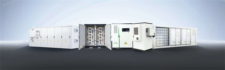
A battery energy storage system (BESS), battery storage power station, battery energy grid storage (BEGS) or battery grid storage is a type of technology that uses a group of in the grid to store . Battery storage is the fastest responding on, and it is used to stabilise those grids, as battery storage can transition from standby to full power in u.
[PDF Version]
Electricity can be stored directly for a short time in capacitors, somewhat longer electrochemically in, and much longer chemically (e.g. hydrogen), mechanically (e.g. pumped hydropower) or as heat. The first pumped hydroelectricity was constructed at the end of the 19th century around in Italy, Austria, and Switzerland. The technique rapidly expanded during the 1960s to 1980s,.
[PDF Version]
The basic working principle of a boiler is simple to understand. A boiler is a closed vessel where water is stored. Fuel, usually coal, is burned in a furnace to produce hot gases. The hot gases contact the water vessel, transferring their heat to the water, which produces steam in the boiler. Then this steam is piped to the turbine. . A boiler (also known as a steam boiler) is a closed vessel in which fluid (typically water) is heated. The fluid does not necessarily boil. The heated or vaporized fluid exits the boiler for use in various processes or heating applications, such as cooking, water or central heating, or boiler. . There are mainly two types of boiler – water tube boiler and fire tube boiler. In a fire tube boiler, hot gases pass through several tubes, which are surrounded. . Steam boiler efficiency is the percentage of total heat from the outlet steam compared to the total heat supplied by the fuel, usually coal. It includes with thermal efficiency, combustion efficiency and fuel to steam efficiency. Steam boiler efficiencydepends upon the size of boiler.
[PDF Version]
The fundamental difference between conventional and flow batteries is that energy is stored in the electrode material in conventional batteries, while in flow batteries it is stored in the electrolyte. . A flow battery, or redox flow battery (after ), is a type of where is provided by two chemical components in liquids that are pumped through the system on. . A flow battery is a rechargeable in which an containing one or more dissolved electroactive elements flows through an . The cell uses redox-active species in fluid (liquid or gas) media. Redox flow batteries are rechargeable () cells. Because they employ rather than or they are more similar to fuel cells than to conventional. . Compared to inorganic redox flow batteries, such as vanadium and Zn-Br2 batteries, organic redox flow batteries' advantage is the tunable redox properties of their active components. As of. . The (Zn–Br2) was the original flow battery. John Doyle file patent on September 29, 1879. Zn-Br2 batteries have relatively high specific energy, and were demonstrated. . Redox flow batteries, and to a lesser extent hybrid flow batteries, have the advantages of:• Independent scaling of energy (tanks) and power (stack), which allows for a cost/weight/etc.. . The hybrid flow battery (HFB) uses one or more electroactive components deposited as a solid layer. The major disadvantage is that this reduces decoupled.
[PDF Version]